| Vert | Bend - 6 options main page |
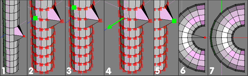
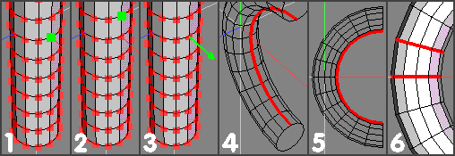
| Bend TopRad
With this option, bend radius is determined by the distance (along the unbent rod) between the Rod Centre and Rod Top (and the AES on which they lie) 1) For Rod Centre, select middle vert shown (facing +Z) with LMB. Selecting a vert on this particular AES also dictates where (the defined) bend radius will act on the bent rod ľ continue with RMB. 2) For Rod Top, select (with LMB) the vert shown ľ 3 sections (therefore 3 units) above the Rod Centre vert. Note that both of these verts are on the same axial edge sequence ľ if they werenĺt, then a twist would be imparted during the bend op. ľ the severity of which would be governed by the offset between which axial edges were used. Using these 2 verts, 3 units apart, on this particular axial edge sequence means that the final bend radius (with bend normal chosen in (3)) will be 3 units between the midway intermediate axial edges ľ not the innermost (or outermost) ones ľ and the centre of the bend (aligned with Rod Centre) ľ continue with RMB. 3) Pick Bend Normal ľ since I want to bend this Rod on an XY plane, the selected vert was chosen, as its normal points in the correct direction. Any of the other 10 verts on this (+X facing) axial edge could also have been used, as their normals all point in the same direction. (Not the 2 end (face) verts, as their normals point in a different direction ľ enable View > Show Normals to check, if not already on) ľ execute with RMB. 4) Drag to 45 deg (hold shift to constrain to 15 deg steps) and accept with LMB. Why 45 deg I hear? :) Well, the distance between Rod Centre / Top is not only 3 units (determining radius) ľ but also 3 rod sections. The angle displayed therefore relates to the angle between the two edgeloops (shown in red) which are associated with the Rod Centre / Top verts selected in (1) and (2) ľ and displayed in red/yellow here. Note that Iĺve shown these verts on their (correct / middle, in View > Z) axial edge sequence as well. 5) Same View >Z of the finished bend, but this time showing the positions (after bending) of the relevant verts on the (red) axial edge sequence. All verts on this (red) edge sequence are now 3 units (radius) from the bend centre. 6) Composite pic of start / finish positions showing how the 3 unit bend radius relates to the 3 unit / section distance between Rod Centre / Top verts as specified in (1) and (2). |
 |
 |
 |
 |
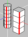
| Vert | Bend Originally made available as a plugin (by napert) it became part of wings core in 0.98.31 - Advanced Menus must be enabled (via Edit | Prefs) Many variations are possible when using these tools ľ the following makes no attempt whatsoever to cover them all ľ only give some ideas about the basics involved ľ the rest is up to you :) It is absolutely essential (imo) that you read and take note of the contents of the info line at the bottom of the wings window :) Since thereĺs some new / slightly different terminology employed, maybe a brief run-through will help. Axial Edge Sequence (AES): This term has nothing to do with the Bend Tools ľ itĺs just my way of referring to the Ĺlines of edgesĺ that run parallel to the main axis of an object like a long cylinder (rod) and actually define the shape of that object. My (tut strip) examples use a 12-sided cylinder so there are 12 AES. (The small pic here shows a couple of typical AES - on a 12 sided / 6 segment cyl and a 4 segment rectangular prism) With these Bend Tools, AESs have particular significance, because important dimensions and characteristics of the final bend are dependant upon which AESs are used for specifying Rod Centre / Top elements (often verts on the AES) Using 2 different AESs for Rod Centre / Top will impart a twist during ĹPlasticĺ and ĹTopRadĺ options ľ the degree of twist related to how far apart (circumferentially) these AESs are. Bend Plastic: With this option, user cannot specify a particular (numeric) bend radius or pivot centre ľ final (object) bend radius is determined by drag extent (angle between planes associated with Rod Centre / Top positions (RC/RT) ) and which AES was used for specifying RC/RT locations.The length of the individual edges on this particular AES stay constant at all times - irrespective of drag magnitude. |
| Bend | Plastic
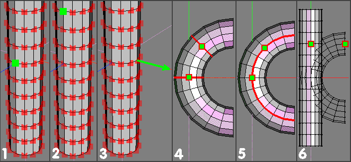
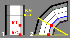
With this option, bend radius is determined by drag extent - controlling angle between edgeloop planes associated with Rod Centre / Top positions (see pic (6))- and the particular AES used to specify the (axial) distance between the elements selected for Rod Centre / End. 1) Select all verts on the rod, apply Vert | Bend > Plastic (LMB option) and choose an element to specify where you want Rod Centre to be located. I chose the vert shown with LMB for two reasons: a) I didn't want any bending to take place around the middle edgeloop of the rod (so any of the 12 verts on this edgeloop would have been ok) - but I also wanted the innermost edges of the bend to lie on the +X facing AES - so, b) Choosing this particular vert (facing +X) uniquely identifies (by being at the intersection of the relevant AES and the middle edgeloop) the necessary location that satisfies both requirements - then continue with RMB 2) For Rod Top, I chose (with LMB) the vert immediately above the one chosen in (1). Doing this means that the angular readout info will refer to this single rod section when using the command (View > Z ortho to eyeball if you want during drag, to observe this angle) Choosing a vert immediately above (on same AES) the rod centre also ensures that the Bend will be a ĹTrueĺ one ľ ie no twist. Note that if the original rod already has a slight twist along its length, then the bend op. will impart another spiral twist - in spite of the same AES being used for Rod Centre / Top (then continue with RMB) 3) For Bend Normal I chose (with LMB) the vert shown ľ whose normal is pointing along the X axis. The arrowhead points towards the bend centre. (then execute with RMB) Note that you can use any appropriate element(s) (along this AES)for defining the Ĺdirectionĺ of this normal, as the point it acts throĺ has essentially been specified by the (position of the) Rod Centre element. As such, I could have used the same vert as in (2) for convenience ľ or any (but end face) other verts on the same AES to get the same result. (normals of end face verts on same AES point in different directions) 4) Drag > 15 deg (hold shift to constrain to a single 15 deg Ĺclick stopĺ) Note that whilst the angular readout only shows the angle between the ends of a single section, the whole Rod still bends (also 15 deg between other adjacent 'pairs of' rod section edgeloops) ľ to form a semicircular bend. (90 deg either side of Rod centre ľ 6 x 15 deg sections either side) (If you drag 30 deg (say) youĺll form a complete torus shape - of smaller diameter - (12 x 30 deg sections = 360 deg) ľ which youĺll be able close by using Object | Weld) The 12 (innermost) edges shown selected are the ones that have not changed length during the complete bend op. ľ each individual edge is the same length after the bend as it was on the unbent rod - note that the verts used for Rod Centre / Top ((1) / (2)) lie on this particular AES. 5) View > Z ortho of the finished bent rod, with the same (innermost) edge sequence shown selected. Choosing the Rod Centre / Top positions on the innermost axial edges (as here) ensures that the greatest dia bend radius (with Plastic option) is created - for a single section, 15 deg drag. Note that if youĺd used a vert pointing along the Z axis (say) to describe the Bend Normal (in step (3)) instead of the one actually used ľ then not only would the final bend lay on a different (ZY) plane, but it would also be a different radius from the one originally described. This is because the Ĺconstant length edgesĺ would no longer lie on the innermost AES of the finished bend. 6) View > Z ortho, showing (side views) of the 2 edgeloops (and related planes) associated with the Rod Centre / Top verts after the bend op. - the included angle is 15 deg. |
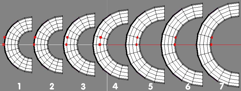
| A composite showing how choice of AES for Rod Centre / Top can affect the bend radius. A 15deg drag has been used in each example. Note how (1) with the Rod Centre / Top elements on the outermost AES produces the smallest dia bend throĺ the other options to (7) where using the innermost AES produces the max bend radius. The distance between each pair of (selected) verts is the same in all seven cases - and the same as the corresponding distance on the unbent rod. Other edges on the same AES are the same length, of course. Option (7) is the same as that created by the previous detailed description - ie Rod Centre / Top verts chosen on the innermost AES. |
|
Pivot Bend
With this option, bend radius is determined by the distance of a (user specified) pivot point and axis. This allows the user to create a bend with known, precisely defined, radius around that specified centre. There is no Ĺconstant edge lengthĺ aspect to this option ľ as with Plastic Bend. 1) To create a pivot point (throĺ which the chosen axis will eventually pass) I selected the vert shown and used Move > X > 1 unit. Another option would have been to create a reference cube (say) and move it to the required position. 2) Select whole object in vert mode and apply Pivot bend (MMB option). For Rod Centre I selected (with LMB) the vert shown ľ for std. (pipe type) stuff it makes sense to choose an element thatĺs on the same plane as the pivot point (if you want to see what happens if you donĺt ľ try it and experiment :) ) - continue with RMB 3) I selected the vert immediately above for Rod Top (with LMB)ľ thus forcing angular readout to be related to one section only ľ thereĺs nothing to stop you using other elements (with more sections) if youĺd prefer a Ĺmulti-section readoutĺ instead ľ continue with RMB. 4) Pick Pivot Axis ľ I chose (with LMB) the vert shown to specify a rotate axis parallel to the main Z axis. Two important points to note here: a)This axis is not THE axis around which the rod will be rotated ľ it needs to act throĺ the pivot point (arranged in (1), here ) first. (see (5) for setup) b)This is a Pivot AXIS ľ not a Bend Normal ľ therefore the vector display shown here is like a (door) hinge axis ľ these 2 vectors - Bend Normal and Pivot Axis will always be perpendicular to each other. Continue with RMB. 5) Pick Pivot Location ľ select (with LMB) the vert shown (the one specifically moved for this purpose, in (1) ) This will transpose the pivot axis (see (4)) to act throĺ this point ľ 1 unit away from (what will be) the innermost part of the bend ľ execute with RMB 6) Drag to 15 deg (hold shift to constrain) and accept with LMB ľ the result will be as shown ľ ie the required bend, 6 x 15 deg segments either side of the Ĺneutral zoneĺ and with the bend rotate axis located throĺ the vert shown selected ľ 1 unit away. Note how the action of this differs from Bend Plastic. Here, the bend radius doesn't alter with drag extent - just the amount (included angle) of bend described / 'uncovered'. If you want to create a bend with an 'awkward' included angle, (117.23 deg? :) ) then a better approach than just described would be to place Rod Centre at one end of the rod (bottom, say) and Rod Top at the top of the rod - then, as you drag, angle readout will refer to the complete bend.(Using middle of Rod for Rod Centre, end of rod for Rod Top would require a drag of half of 117.23 :) ) 7) After Ĺtidying upĺ ľ just select the vert displaced in (1) and Move > -X the same distance as it was originally moved, ie 1 unit here. If (say) youĺd wanted the bend centre to be 1 unit away from the centre of the rod, then (if using the same approach) instead of selecting (and moving) the vert shown in (1) then selecting the appropriate vert facing +Z (on the neutral zone) and moving X > 1 unit would have done the job. (Or, as previously mentioned, use some other preferred method, like a ref. block ľ as long as you donĺt get a Ĺcreative blockĺ, summatĺll work out :) ) |
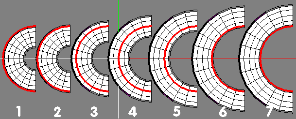
| This composite, shows the various solutions for a 3 section (3 wu, here) distance between Rod Centre / Top and illustrates the range of bends available.
For each of these seven possibilities (all 15 deg drag), all verts lying on the selected AES (in red) are at a radius of 3 units from the bend centre ľ even though the main Rod centreline to pivot distance (radius) of each object is different. If consistency / predictability of bend radius in practice requires some simplification ľ then maybe just stick with the middle edge option (4)? This's it for now (July7), but because of the complex nature of these tools, it is likely that this page will be modified / amended etc - check the 'updates' section (bottom right) of contents page for notification of such changes. All of the above is based on the assumption that the user wants their bends to be 'true' ones - ie 'untwisted' - such things are possible (and much more :) ) - but, from my pov, will have to wait :) Note that I've used 2 step selection procedures throughout the above explanations - ie select with LMB to get / show a static vector, then RMB to continue etc. In reality, with appropriate prefs enabled, all of this would be done with just RMB select / continue / execute - thus saving mouse clicks :) |
| Bend | Plastic |
| Bend | Plastic results showing how the result is influenced by the choice of which AES is used for Rod Centre / Top. |
| Bend | Pivot |
| Bend | TopRad |
| How final bent object is affected by choice of AES |
 |
 |
 |
| 1)Shows RC/RT positions, on the same (blue) AES and Bend Normal (BN) aligned with X axis.
2)After dragging 30 deg (angle between planes associated with RC / RT ) Bend centre is computed using this angle (yellow lines) and the length of (blue) edges on the AES used for specifying RC / RT. Individual (blue) AES edges stay the same length throughout the whole Bend Plastic operation. (3 segment, 12 sided cylinder used for clarity) |
| Bend Pivot:
User specifies a bend radius (and axis) and the Rod is bent in accordance with these parameters. An external reference block or similar datum / feature will often be used to provide the necessary information. Bend TopRad: User specifies a bend radius by selecting elements on the unbent rod (via Rod Centre / Top) that are the same distance apart as the required bend radius. Where this bend radius acts is also influenced by the particular AES used for Rod Centre / Top. Rod: The object being Ĺbentĺ ľ since this is quite often likely to be a cylinder or cube (scaled along an axis) and is therefore much longer than its diameter or cross-section, itĺs a logical choice. Rod Centre: The region of the rod where no bending takes place during the bend operation. This may often co-incide with the middle of the rod (if bend symmetry is required) ľ but it certainly doesnĺt have to be there by necessity for the tool to work correctly. Rod Top: A position on the rod that (together with) the rod centre, determines certain aspects of bend behaviour and is therefore significant for several reasons: The distance (No of rod segments) between Top and Centre influences the angle being displayed (in top left info display) during the bend dragging stage. Eg If there is only 1 rod section between Rod Top and Centre, then angular display will refer to that section only ľ even though the whole (selected) rod will bend. For ĹTrueĺ ľ ie non-twisted bending to take place (in Plastic and TopRad options), the Rod Top position has to be on the same AES as the element chosen for Rod Centre (or appropriately aligned in some other way if axial edges (or their verts) arenĺt used for specifying these positions) - In Bend | TopRad option ľ the Rod Top > Centre distance determines the bend radius of the final object ľ again, also related to and influenced by which AES these elements lie on. Bend Normal: This is a line passing through the rod (centre) and the centre of the bend. In wings, the arrowhead on the end of the displayed vector points towards the centre of the bend (or centre of a circle that will have the bent rod as (part of) its circumference. Pivot Axis: The axis around which the Rod will be rotated to form the final bent object Note that this axis is perpendicular to the Bend Normal Pivot Location: The Ĺanchor pointĺ (or Ĺlocal originĺ) through which the (previously specified) Pivot Axis passes. These two steps (pivot axis / location) therefore uniquely determine all relevant aspects of how the bending op. will take place. The final bend radius will of course, be determined by the position / distance of this pivot location from the Rod Clamped bend options The ĹBendingĺ aspects of these 3 options work in the same way as the 3 std. / Ĺunclampedĺ options (so no specific user details / tuts) ľ the only difference being that they allow the user to specify positions (on the Rod) where bending stops and straight rod continues. This allows the user to easily obtain results like a ĹUĺ shaped object (say) ľ where a 180 deg bend region is located between 2 straight pieces of rod ľ this of course, is only one simple example of many :) Top / Bottom Clamp points: The points specifying where rod bending stops. If a clamped option is chosen, the clamping points do not have to be equi-spaced about the rod centre, nor do they both have to be Ĺusedĺ to control the final shape of the bent rod. It is possible to specify clamping points such that there is straight rod on only one side of the bend region. The basic ĹRodĺ object for all the following examples has been created in the following manner: Create 12 sided cylinder and select object Scale Y > 600% Select all axial edges Cut 12 Connect The object should now be 12 units high, with 12 sections of 1 unit length ľ as well as being a cylinder having 12 sides. Thereĺs nothing particularly special about this shape ľ but having 1 wu long sections make it easier to see (imo) which bits are being altered / staying constant ľ if you want to experiment :) Having View > Show Normals enabled during experimentation / messing around might also be an idea if youĺre not too familiar with the directions that normals occupy? If you decide to use a different object for messing around (and no reason why not) ľ then ľ if you want to keep things simple for yourself ľ make sure that the sections of the rod where the bend actually takes place are equi-spaced. For most (pipe) bend situations thisĺll be common sense anyway :) (Less important if using the clamped options, as there is less (if any) need for intermediate edgeloops between those defining the regions of straight rod) |