| Using the Vertex | Deform ->Inflate command via the LMB option will typically 'grow' (or shrink) a group of selected verts in a manner determined by the bounding box that contains these (selected) verts. If you drag to 100% the selected verts will then lie on a 'true' spherical curved surface - but you won't have any real control over the centre and radius of this spherical shape. Whilst this may be OK for some tasks, there are many others that require a centre and radius to be precisely specified / defined. The purpose here is to describe the RMB options for when such occasions arise. Although both LMB and RMB Inflate options work in full 3D (to place selected verts on a surface that tends towards a spherical one) - if the verts lie on a 2 plane, then Inflate -> 100% will 'circularise' the verts on this plane. |
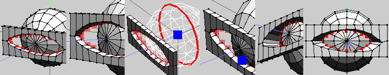
| Using Vertex | Inflate to align geometry to a specified radius and centre Assume we want to conform / align the geometry of an eye surround (inner verts shown selected, (1)) to the curved surface of the eyeball (sphere) 1). Shows shows the verts to be aligned. 2). With these verts selected, invoke Vertex | Deform -> Inflate (Use RMB) 3). Select centre (of eyeball) by choosing central edgeloop of eyeball sphere (select one edge, press L) press RMB to continue to next stage(define radius). 4).Select a vert to define the radius with RMB (or use method(s) previously descibed in first example if multiple elements required to define radius) 5-6) Drag mouse to inflate 100% (use shift to constrain) and all the selected verts now lie on a spherical radius, centred about the 'eyeball' centre. If you anticipated doing regular adjustments like this, it might be an idea to store the eyeball centre selection? |
| 1).Assume you have a collection of (displaced) verts lying on a 2D plane that you want to conform / correct to a circle (or part of) 2). Select the appropriate verts to modify (as in 1) and invoke Vert | Deform -> Inflate, using RMB. Wings now requires you to first define the centre for the inflate op, then choose a point, whose distance from the centre will determine the (spherical) radius upon which the selected verts will lie after completion of the inflate op. In this (2D) case, the verts will lie on a 'circular slice' through the centre of the 'inflate sphere of action'. The plane on which this 'slice' lies (here) will be parallel to an axial Y plane. 3). Select a suitable centre. I chose the vert in the middle, indicated by the blue square. If you are choosing a single element (as here) to specify the centre, you can do it in two ways: a) Select the element with LMB, then press RMB to accept this selection - and also continue to the next stage. b) Select the element with RMB - this not only selects, but also accept and continues to the next stage - all in one keystroke. If you cannot define your required centre with a single element, use LMB on all necessary elements (say 2 verts, on each end of a diameter) and accept / continue (to next stage) with RMB - or chose first vert (in same situation) with LMB and second with RMB to accept / contiue in one go. 4).Select a vert to define the radius (again shown as blue square). You can use the same procedure as before - do all selecting with LMB then accept / execute with RMB.- or (if a single element) select / accept / execute with RMB 5-6) Drag mouse to inflate 100% (hold shift to constrain) and all the selected verts now lie on a circle, centred on the specified point - it should be noted that they won't necessarily be equi-spaced. |
 |
 |
| Using the Inflate command RMB options to conform geometry. |
| Using Vertex | Deform -> Inflate ->100% to circularise geometry to a specified centre and radius in 2D |
| Using Vertex | Deform -> Inflate -> 100% to spherize geometry to a specified radius and centre in 3D |
 |
| Forming a circular face onto a square, using inflate |
| 1).....Inset (square) face 2).....Press 'e' for edge mode 3).....Cut 2 4).....Select other verts (can either just click on other verts, or select inner face and press v - this method easier for (8), especially - imo) 5).....Vert | Inflate -> 100% (use LMB option) 6-9)..Repeat above ops if need to get extra detail. Cutting 4 at stage (3) gives poorer results than doing it in 2 stages as above. Tighten / inflate route (for non square face) is ok if edge length commonality isn't critical, as inflate produces verts on a circle - but not necessarily equi spaced:) |
| Inflate |
 |
| 1) Create a 4 by 4 grid primitive and select the verts shown. I'm assuming you wanted semi-circular ends and all 'corners' to be symmetrical. You'll have to use different centres / radius from mine if these assumptions are incorrect. 2) Vert | Inflate (RMB to choose centre and radius options. Select vert as shown (in blue) as the centre. 3) Select vert shown (in blue) to define the radius. 4) Apply Inflate -> 100%. This moves all verts as shown. 5) View Y (ortho) and use Tweak (or Move Free) to pull this vert back into the fold. Arrange other verts to suit (I didn't bother) 6) Select the lower face and use Face | Mirror to get a semicircular chunk. 7) Select right hand face(s) (of grid) and use Face | Extrude Region -> X (0.5) twice. (use shft D for second extrude) If you mirrored now, you'd end up with a 12 by 8 instead of an 11 by 8. Select all edges as shown. (select one then use G) 8) Apply Edge | Connect then Edge Loopcut. Discard the unwanted piece. 9) Select end face and mirror to get complete object. Select unwanted edges along the mirror face, dissolve. Select whole object, use cleanup. Select all faces of your shape and use Face | Extract -> Y (say). Dump (hide) the grid. If you want edges on the underside of the extracted object - select underside face and mirror. |
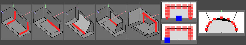 |
| Just used one way (of many) to make the basic well. 1). Arrange some basic geom. at the location, select the 4 edges shown and Edge | Bevel zero. 2). Select corner edge. 3). This edge can now be moved to form the upper (inside) corner of the wheel well (Move X,Y) 4). Final position for this 'inner corner' edge. Select whole object and apply Cleanup (to get rid of extra verts created during the zero bevel op - eyeball top left readout) 5). Select the outer 3 edges that will eventually form the wheel arch and cut 4 (I used same No for simplicity - use whatever you feel necessary to define the correct shape) 6). (Upper pic) Select all verts except bottom 2, apply Vert | Deform -> Inflate, use RMB option, choose 2 verts at lower corners to give a centre location (blue square in middle) 7). Set radius by choosing vert in corner 8). Drag 100% (weird bit is a display artifact - this'll disappear after more edges added etc) Repeat for inside 'wall' if required, after cutting in some verts. Join up verts to regain quad integrity etc |
| Forming a semicircular wheel arch for a car. |
| Forming 90 deg sectors as part of a grid. |
| 1 |
| 2 |
| 3 |
| 4 |
| 5 |
| 6 |
| 1 |
| 2 |
| 3 |
| 4 |
| 5 |
| 6 |
| 4 |
| 5 |
| 6 |
| 7 |
| 3 |
| 2 |
| 1 |
| 8 |
| 4 |
| 3 |
| 2 |
| 1 |
| 5 |
| 6 |
| 7 |
| 8 |
| 9 |