 |
 |
 |
 |
 |
| 1). A basic sort of wedge to produce a flowery / petally sort of object. Nothing special about this - but note that (mirror) surfaces don't necessarily have to follow any partic line (as with first example) - provided mirrored objects form a whole, you can do what you like - plenty of scope. 2). A slightly modified version of (1) - a little further down the line - and some comments about the approach used. a. Create a cylinder, rotate Y -> 11.25 deg (to get faces opposite centre and periphery) Scale -> Z to suit, Inset both end faces and Bridge. b. Select the outer end face of the cylinder and Extrude Normal a little - to form the block with the blue end face here. To form the ring segment at the periphery - Select whole object, duplicate on the spot (hold shift) then do a vector rotate -> Y on the dupe, using RMB option and select the top face of the cube to provide the reference point. I rotated 45 deg here. c. Select the inner faces on the 'blocks' formed in (b) and bridge between them. Select all 4 edges of newly bridged geom and connect, then bevel (as in first example) to form the face required at position (c) Select edges to either side (8 in total), cut 3 and connect to form the other six 'sections' - (3 of which shown between (b) and (c) ) 'Circularise' the edges by using Vert | Deform - > Inflate -> RMB option. Use the top and bottom faces of the cube to provide relevant centres and obtain radii from appropriate verts on the blue face at (b) (Four inflate ops - 2 top, 2 below) d. Extrude normal inner face a little towards (f) then repeat and scale X end face to form the (nearly) triangular face at (f) e. Select edges, connect and bevel to form (4) new edgeloops. f. Bridge between faces at (e) and (f) also (e) and (c) - forgot about the 'triangular -ish' block at (c) - make as the one at (f) g. Bridge this 'stub' across to the dupe Loopcut at appropriate places to form a single section - (can do a trial dupe/rotate) to check all's ok if you want Ensure faces that will eventually be welded are single faces - no intermediate edges - eg at (c) remove intermediate edge to form a face with 6 verts - or organise 'wedge' in a different manner - like (1) All the above is easier to do than describe, imo - once you have the basic shape, mess around, but don't touch the 'weld / joint' faces. (Although mistakes can be rectified relatively easily) 3). Result after Duping / rotating etc - more details about this in the Bikewheel tut for doing the spokes. |
| Wedges Sometimes it might be worth considering making a single 'wedge' of an object - especially if it's going to be relatively detailed - and then forming a complete object by mirroring / welding etc. All manner of ways to do this, of course - this is only one. |
| 1). Create cube, select end face and apply Face | Scale -> X (used 20% here) 2). Apply Face | Extract Region -> Z. Moving -1 unit will place the extracted face at the origin. (I also hid the cube) 3). Select the other face and apply Face | Lift, use LMB option, select the top edge and drag to 15 deg (constrain by holding down shift) 4). Select all 6 edges 5). Apply Edge | Connect (press C) 6). Apply Edge | Bevel and drag as required to move the 2 new edgeloops outwards. 7). Press L to select the 2 new edgeloops 8). Bevel these edges a little. 9). Select inner edgeloops. 10). Apply Edge | Scale -> Z to suit. You now have a basic 'spoke / feature' - one of 12 in this case (use appropriate angles for other numbers). 11). Mirror and weld to form a semicircular object, dissolve the unwanted edge at the centre, then mirror / weld to form a complete object. Provided the 'mirror' faces on the basic wedge aren't disturbed, you can do anything you like to the rest - if you want to get a better idea of what the 'whole' looks like - just mirror, then undo? If the object is very complex, working on a single wedge will make life easier (unless you have a very fast machine) - as, indeed will saving just a single item which contains all the necessary information. |
| Something similar - but different. |
| 4). The sort of thing you'd expect to see during the proceedings. If you do mess up 'weld / join' faces etc - make a dupe of what you've got (including foul up) loopcut off the mess, re-bridge between good (wanted) bits, lop off irrelevant stuff and carry on. 5). I then made the fatal mistake of deciding to continue messing around with the basic shape :) Scaled (Y) the inner 'branches' a bit and formed holes in the orig cylinder by insetting and bridging etc. 6). Somewhat further along - am now starting to think 'twin-engined scout ship' or something similar - but still holding onto the wedge - for some daft reason. |
| 7). Even further along - with very early section for comparison - left gap to highlight where one starts, other stops etc. Been adding edges etc to keep shape during smoothing (no hard edges used). 8). Underneath view of above situation. |
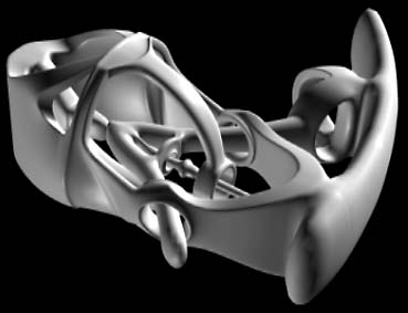
| OGL render of latest version - will now abandon any further thoughts of maintaining 'wedge' approach and use this as a basis for something else - something mechanical-ish with an organic sorta 'feel' - maybe. Blobby areas caused because only a single wedge has been smoothed - and other bits not finished, anyway. |
| Following comments re a 'flowers' type of object (Wings forum, Renderosity) - thought I'd give this method a try for this - but it did get a bit out of hand :). Since I didn't start out with a tut in mind (but saved intermediate files), this'll be a little different from 'usual'. |