 |
 |
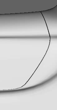
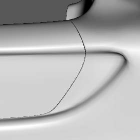
| Basic cage both pix. Not saying this is 'the' way to go about it - just the way I'd approch it (also been having issues with something of my own and using similar methods. :) ) Wasn't completely 'with' your pix - a bit 'too' zoomed in - thus removing some useful references - for someone that's not been 'living with it' Moving the bounding edges with respect to the 'main' ones will control 'sharpness, of course - you can even get a varying, 'tapered' radius by moving the boundaries out of parallel to the main. Since i'm not 100% sure what you're after - and it's late here - consider this some sort of 'starter' - rather than 'the answer' - no doubt others will throw in their 2p worth anyway :) ......so I just concentrated on the edges which appeared to be hard. The gap between the edges is just an arbitrary one - close enough to show the idea - some may well need to be closer together - but would then be difficult to see - for illustrative purposes. Personally, I'd try to keep the main edge + one either side of it - and all quads if possible - I'd keep clear of mitred corners (like those produced by inset) for this sort of thing. This sort of stuff isn't easy (imo) and you'll probably end up with more geom than you orig thought ...... good luck :) (Even if I've got things totally wrong - re what you're trying to do - I still use this approach for this sort of stuff - mess around and give it a try) |
 |
 |
 |
 |
 |
 |
| This is going to be quick and dirty:) Only did the back half of the door recess Connected all the cross edges and bevelled to max extent to get the 2 new edge sequences in approx right place moved them using RMB move so they're approx 0.037 wu away from your orig edge system connected again and made the 'fan' affair at the top - not brilliant, but wanted to ensure all the periphery verts were joined to something when I continued the new edges around |
| A bit of weirdness (imo) at the rear (bottom) of the door recess - I reconnected the LH edge to the adjacent vert and used cleanup to dump the duff one. |
| If this was mine, I'd do something about the selected faces - especially those in the more critical areas - don't give the little critters any more chances of going to places they shouldn't - during smoothing :) |
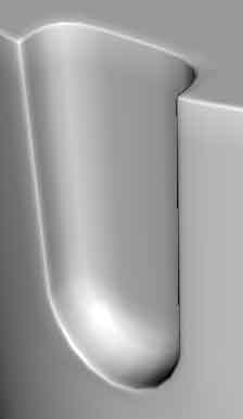
| 2 smooths ogl render Your door, including hard edges My recess - after being bodged as above - no other messing around except as described. |
| I'm going to leave it at that for the time being - the other 2 areas (only briefly glanced) would be attacked in roughly the same sort of way - have a go - and if you're still having problems, holler :) If fed up, give it a rest and come back to it sometime....... Not saying this is right - just how I'd go about it - and have, in this partic. case :) |
 |
 |
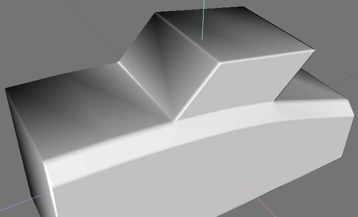
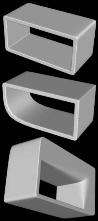
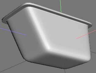
Basic shape with 'mech bevels' around all edges where needed. Adjusting the selected edges to alter the shape after smoothing (twice) - but still keeping the other edges in the same position to keep the corner sharp(ish) Slightly modified shape (to demo effect better) - adjust selected edges to alter the rad along the length of the edge. All RHS pix after being smoothed twice - these are basic approaches - but note how the edges inside the hole have mech bevels as well. |
 |
 |
| No magic bullet answer for this - above is just one of quite a few variations. Think you've got to be prepared to have a fair bit of extra geom - if you want to maintain precision of the appropriate shapes - but that's just imo. If the surrounding (cylindrical) surface is broken up by other features, I reckon some of the (slightly) simpler solutions will do - all depends on what you're after. Using Inflate (RMB option) to re-align newly introduced geom between original axial edges (to get all verts on a true circular circumference) is also worth consideration imo. (that's why there's a slight discrepancy on the w/f - I adjusted an outer - but not the inner :) ) RH pic smoothed twice, btw. |
 |
 |
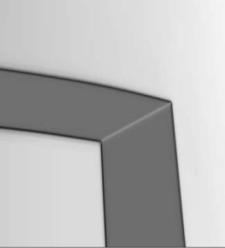
| .9). Close up of the top left outer corner of the recess - after the bevel op in 8. 10 - 12) Repeat the same process for these horizontal edges as was done in 6 - 8. Ie - select edges, connect, bevel 3.4. 13). Close up of the top left outer corner of the recess. 14). Close up of the top left inner corner of the recess. Try a smooth and see what happens now. Selecting the edges either side of the middle edge(s) and adjusting them - individually (or together) will allow you to control various aspects of what is produced after smoothing Additional geometry may, of course, be introduced to obtain various results - but this demonstrates the basics of what is needed for this sort of thing. Mess around and have some fun :). |
| Mechanical bevel - internal recess. This is just one of many ways to construct a basic mech. bevel to demo the sort of thing that will be required to maintain 'sharp' corners - without using Edges | Hard. |
| 1). Create cube and apply Face | Inset -> 30% (hold Cntrl to constrain to 10% 'steps') 2). Keep the (inset) face selected and then re-apply Face | Inset -> 1% (use D - repeat last op, Shft + Cntrl constrains to 1% steps) 3). Apply Face | Extrude -> Normal -> -0.02 units (Figs 1, 2 and 3 show the top left (outer) corner of the recess) 4). Repeat extrude op (press D) and drag to -0.6 units 5). Repeat extrude op (press D) and drag to -0.02 units. (In figs 4 and 5, the selected (red) area shown is the bottom of the recess being formed into the cube) (The basic recess has now been formed, but more edges are required to stop the recess distorting during smoothing - try a smooth and see what happens?) 6). Select all vertical edges (select one, press G) - don't actually need ALL edges, just easier to describe :) ) 7). Apply Edge | Connect 8). Keeping the newly created edges selected, apply Edge | Bevel -> 3.4 units - this should move the 2 new edge systems towards the (internal) corners (see 9). |
 |
 |
 |
 |
 |
| A couple of ideas for dealing with 'nested' corners - keeping the geom on the 'thingies' themselves (rather than the main mesh) - and all quads - no claim for perfection, but might be a starting point :) |