• Website
  • Search
  • Member List
  • Help
  • Old Forum
  • Social Media
    •   @Wings3dOfficial
    •   @Wings3dOfficial
    •   Wings3dOfficial
    •   Wings3dOfficial
  • Register
  • Login
  • Website
  • Search
  • Member List
  • Help
  • Old Forum
  • Register
  • Login
Wings 3D Development Forum Wings 3D Interface & Usage v
1 2 3 4 5 … 32 Next »
How to fill a gap between 2 objects? (different shapes)

 
  • 0 Vote(s) - 0 Average
How to fill a gap between 2 objects? (different shapes)

lennart
Offline

Junior Member

Posts: 13
Threads: 7
Joined: Jun 2013
#1
10-06-2024, 03:06 PM
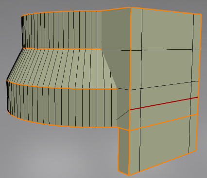
Designed a little flash light holder with a tube and a bracket for the 3D printer. Made two body's, see screenshot.

How can i fill the gap between these two objects? Tried several options, but none of them seem to work. What is the right way to fill the gap between these two objects?
   
~~~~~~~~~~- ~~~~~~~~~~
Main goal: 3D-printing on a Ender
micheus
Offline

Forum's Admin and Support | Bug fixer
Posts: 3,676
Threads: 183
Joined: Jun 2012
#2
10-06-2024, 06:52 PM
(10-06-2024, 03:06 PM)lennart Wrote: Designed a little flash light holder with a tube and a bracket for the 3D printer. Made two body's, see screenshot.
If I understood how you want to fill that gap, I think you can try this one:
[Image: Mixing-Objects.png]

I recommend to move out the overlapping edge we created in that position, then you can correctly mark hard the edges without missing anyone and have problems if you smoot your model on export.


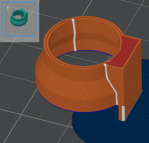
For 3D printing, objects need to intersect each other so that the slicer can process them accordingly.
Here is the Orca Slicer preview:
[Image: tw.png] @MicheusVieira [Image: yt.png] @MicheusVieira [Image: da.png] Micheuss [Image: ig.png] micheus4wings3d
* Wings3D Team stands for: Björn and Dan
ivla
Offline

Member

Posts: 62
Threads: 7
Joined: May 2023
#3
10-07-2024, 11:10 AM (This post was last modified: 10-07-2024, 11:55 AM by ivla.)
Another method, one body without combining:
(working on a half-pipe, selection color is orange)
[Image: 00.png]
Select come faces:
[Image: 01.png]
Extrude it by X:
[Image: 02.png]
Flatten faces by X, dissolve all faces to one and move face as need by "absolute move":
[Image: 03.png]
Select and dissolve internal edges and vertices:
[Image: 04.png]
[Image: 05.png]
Select upper corner point and "intersect" along this edge to the lower vertice position:
[Image: 06.png]
[Image: 07.png]
Select and extrude by X face to form a base of the flange:
[Image: 08.png]
Select and extrude by normal side face(s) to form the flange:
[Image: 09.png]
Now you can set the flange size as you need - use absolute move and/or scale.

Cleanup "internal" face:
[Image: 10.png]
[Image: 11.png]
...and mirror on it, then weld a whole object:
[Image: 12.png]

Side faces on a "bridge" part will be non-flat so you can divide it by hand or leave this action for STL exporter.
ivla
Offline

Member

Posts: 62
Threads: 7
Joined: May 2023
#4
10-07-2024, 12:29 PM (This post was last modified: 10-07-2024, 12:40 PM by ivla.)
Another way to do it.
Filling the gap with "Bridge" operation.
Result will be clean if both bridging faces will have the same number of vertices.
Make pipe and flange, place it to the right position.
Make additional vertices on the flange face:
[Image: 00.png]
Turn on "wireframe mode" for the flange, select some face on the tube:
[Image: 01.png]
Dissolve it:
[Image: 02.png]
Select "unnecessary" vertices on face:
[Image: 03.png]
And delete it:
[Image: 04.png]
Then turn off wireframe mode and select two faces to be bridged:
[Image: 05.png]
Make "bridge".
[Image: 09.png]
Note that some faces on top and bottom requires a correction:
[Image: 06.png]
Use face dissolve and edge delete on top face:
[Image: 07.png]
and bottom one:
[Image: 08.png]
micheus
Offline

Forum's Admin and Support | Bug fixer
Posts: 3,676
Threads: 183
Joined: Jun 2012
#5
10-07-2024, 04:29 PM (This post was last modified: 10-07-2024, 04:31 PM by micheus.)
lennart, just to show what ivla meant when he said "Side faces on a "bridge" part will be non-flat ..." in the first approach:
[Image: 3dprinting-issue.png]

That hatching area in yellow will not be flat. Any approach in which you use starting from the cylindrical object will result in something like that and you should work on it to ensure you get perfect flat faces.
[Image: tw.png] @MicheusVieira [Image: yt.png] @MicheusVieira [Image: da.png] Micheuss [Image: ig.png] micheus4wings3d
* Wings3D Team stands for: Björn and Dan
ivla
Offline

Member

Posts: 62
Threads: 7
Joined: May 2023
#6
10-08-2024, 02:54 AM (This post was last modified: 10-08-2024, 03:56 AM by ivla.)
It's not an issue.

Side face will be non-flat because all its vertices isn't on the one plane.
STL exporter will triangulate this face.
But if we want the predictive result then we have to do it "by hand".
[Image: 08a.png]
Three edges (black) should be added.
It divide whole face into the four parts, three of them will be vertical and one with small slope (so it can be printed without a supports).

If that face should be vertical "at whole" we can use "plane cut" operation to get a "straight vertical" section to extrude.

BTW, "negative" slope up to 45 degrees can be 3d-printed without any problems.
micheus
Offline

Forum's Admin and Support | Bug fixer
Posts: 3,676
Threads: 183
Joined: Jun 2012
#7
10-08-2024, 03:18 PM
(10-08-2024, 02:54 AM)ivla Wrote: It's not an issue.
Sure it's not a issue.
But, if I would like that side face was perfectly flat for aesthetical reasons, then I would ensure it's flat (I'm a perfectionist, what can I do?! Biggrin)
[Image: tw.png] @MicheusVieira [Image: yt.png] @MicheusVieira [Image: da.png] Micheuss [Image: ig.png] micheus4wings3d
* Wings3D Team stands for: Björn and Dan
ivla
Offline

Member

Posts: 62
Threads: 7
Joined: May 2023
#8
10-15-2024, 10:30 AM
(10-08-2024, 02:54 AM)ivla Wrote: If that face should be vertical "at whole" we can use "plane cut" operation to get a "straight vertical" section to extrude.

By the way. Is it possible to make "Plane cut" on the selected faces, not on the whole body?
micheus
Offline

Forum's Admin and Support | Bug fixer
Posts: 3,676
Threads: 183
Joined: Jun 2012
#9
10-15-2024, 04:16 PM
(10-15-2024, 10:30 AM)ivla Wrote: By the way. Is it possible to make "Plane cut" on the selected faces, not on the whole body?
It already does!
You must be in Face selection mode [F].
[Image: tw.png] @MicheusVieira [Image: yt.png] @MicheusVieira [Image: da.png] Micheuss [Image: ig.png] micheus4wings3d
* Wings3D Team stands for: Björn and Dan
ivla
Offline

Member

Posts: 62
Threads: 7
Joined: May 2023
#10
10-16-2024, 02:58 AM
Thank you.
« Next Oldest | Next Newest »

Users browsing this thread: 1 Guest(s)


  • View a Printable Version
  • Subscribe to this thread
Forum Jump:

© Designed by D&D - Powered by MyBB

Linear Mode
Threaded Mode