My assumption here is that you've just started using Wings or you're thinking about downloading and trying it. (If the latter, go ahead and try it - you've little to lose but much to gain imo :) ). Everything here is associated with commands and operations in Wings - nothing else.
This basics section has no intention of going through all the commands one by one in the 'usual' manner. This is the job of the User Manual, so please read that (as well) if you prefer this sort of approach.
(Whilst Wings releases are frequent, most of the core modelling functions haven't changed too much since the release of the UM)
Please read the Wings 'Help' section and info line (at bottom of screen)). The info line displays details of available options for the command in use and general navigation comments. Taking note of this information whilst using advanced menu commands (magnets and/or vectors) is definitely recommended. L,M and R refer to Left, Middle and Right mouse buttons respectively - not keyboard keys. (Advanced menus are activated via Edit | Advanced Prefs)
The following abbreviations will be used for mouse operations:
RMB: a single click with the Right Mouse Button (a 'click' being a press and release operation).
MMB: as above with Middle Mouse Button.
LMB: as above with Left Mouse Button.
To repeat - read the info line contents and try the various options available:)
Cube to finished model.
If you're new to 3D modelling and sitting in front of Wings, (with a blank screen) you could well be wondering what to do - and how to start with a cube and end up with a finished model. (Finished in this case referring to geometry only - ready to be textured / mapped etc)
In my opinion, the cube to finished model workflow is essentially concerned with two things, the introduction of new geometry (verts, edges, faces) to the cube and the manipulation of geometry to get the required shape.
Introducing new geometry provides sufficient information (verts etc) to adequately define the required shape
Geometry manipulation facilitates their correct placement in 3D space and relative interconnection with neighbouring verts.
Getting started
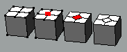
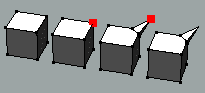
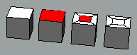
To get started you need a cube (or other primitive) - RMB in the empty Wings window and a choice of primitives will be displayed - choose cube (say)
To do anything with what you've just created, you'll need to select something on the cube - move the cursor over the cube and select a highlighted element (any type) with LMB
Using RMB now will display a list of commands / tools appropriate to the type of element selected. These will be (slightly) different for the 4 selection modes available (vert / edge / face / body)
Pick one and experiment. Try another���and another :)
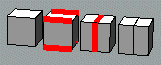
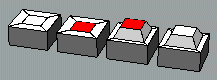
Introducing new geometry.
The two main ways of introducing new geometry are:
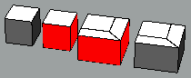
1) Cut up what already exists into smaller pieces.
2) Leave alone what's already there and add some more
Some (simple) examples are shown below
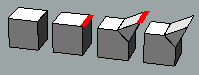
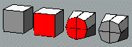
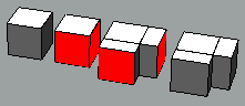
Adding to existing geometry (2) is mainly done by an Extrude type command (or a derivative (eg Bump, Lift). Joining one bit of geometry to another is also possible with the Bridge command. Mirroring creates a laterally inverted duplicate half about a chosen face.
Some (simple) examples are shown below.
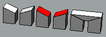
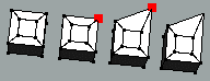
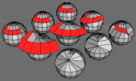
Forms a face at the location of the selected vert. There will be the same number of edges around the newly formed face as there were edges joining the original vert to the surrounding geometry. Edge and Face | Bevel produce different results, but essentially 'cut up' existing elements into smaller pieces. Geometry 'shape' will be extensively modified under certain conditions - eg bevelling a cube vert/edge/face.
Upon applying this command, Wings will form a 'boundary' edge around the chosen vert, which then defines the base area for the extrusion.Use the +/- keys during dragging interactively modifies (grows / shrinks) this base, whilst drag extent alters extrusion height along the verts normal. (+/- keys were not used for this example)
Joins selected edges through their mid points or joins selected verts with edges.
Selecting one edge, then pressing G (select edge ring) to select all appropriate edges around a cylinder (say), before using Connect can save much time. (Using Edge | Cut 2 -> 10 (use number keys for shortcuts) on the selected edges prior to using Connect is also very useful )
Moves the selected edge along its normal, creating extra geometry between its new position and the boundary edges formed around its original one. Use +/- to modify the boundary area.
Forms a new face similar to that selected by constructing an equal width 'perimeter boundary' around the selected face.. If multiple faces are selected, inset will only work on an individual basis when the command is applied. (Single faces that are 'U' shaped won't inset correctly - using Face | Intrude as the basis of a workaround is one approach) Since this command is percentage based (rather than a linear dimension), be aware of issues when insetting a sequence of 'same size' steps. (See 'assorted')
Similar to a Face | Extrude (region) command but works with single (or multiple) face selections. The essential difference being that Bump forms a boundary area halfway between the selected face(s) and neighbouring geometry. Using +/- keys will grow or shrink this boundary area. Pressing the (- ) key to its fullest extent (10 steps from default) will produce a shape equivalent to that resulting from an Extrude op. Although appearing similar, the Bump result will have more geometry and will therefore smooth differently.
Creates 4 faces for every face selected and ensures that they are correctly incorporated into the surrounding geometry by also forming additional supporting geometry. The shape of the object will be modified, unless the selected face and sufficient edges of the surrounding geometry have had their edges hardened. (Edge | Harden)
Creates extra geometry between 2 faces with equal vert counts. Can also be used to create 'tunnels' thro' objects if the selected faces are on opposite sides of an object. (eg Select cylinder end faces, Face | Inset -> 50% and Face | Bridge) Selected faces must not be adjacent or facing the same direction.)
Commands that form a 'boundary edge loop' will do this, irrespective of whether geometry is 'dragged' or not. Constraining drag effect to zero thus provides further 'cut - up' options.
(Inputting zero may seem odd to a newcomer, but it has many valuable uses within Wings -
eg Create 2 cubes (and move apart), select all 12 edges on one cube and apply Edge | Bevel -> zero. Go into object mode (press O), select both cubes and apply Object | Smooth - note the difference.
These two commands can sometimes create geometry that (superficially) appears to be similar. Subsequent operations on the geometry (especially a smooth op) will, however, produce radically different results. The user should be aware of the difference.
When you have to remove elements of unwanted geometry / features, then use one of several tools that exist for this task (Delete, Dissolve, Collapse). Reading the lower info line will (as usual) provide details of how these commands work. dissolve/collapse
If you need to get drastic, one method is to select a complete edgeloop (continuous sequence of edges) and apply Edge | LoopCut. This will result in 2 (or more) separate objects that can be deleted (or just hidden). Provided you don't mess up the 2 faces formed by the LoopCut op, they can be re-joined by using Object | Weld. (This loopcutting / welding technique can also be used to separate (and temporarily hide) portions of a model to allow easier editing to take place, since Wings currently doesn't support hiding individual polys) welding
Move
This command moves selected geometry in a manner appropriate to the chosen sub-menu option. Note that Move ->Y (say) means that the selected element is typically moved along a line (axis) parallel to the Y axis - not the actual Y axis itself.
Two options that deserve further comment are Face | Move -> Region and Move -> Free.
Face | Move -> Region allows the user to move several selected faces (sharing at least one edge with adjacent faces) along a single normal (unlike Move | Normal) The single axis (along which movement takes place) is derived from the edgeloop surrounding the selected faces.
Move | Free constrains all movement to 2D planes that are parallel to the (monitor) screen plane. Since the 'Move Free' plane isn't always parallel with one of the XYZ axes, using this command can easily produce unwanted and unpredicable results. 'Free' commands are discussed in greater depth elsewhere. (see views)
The selected vert is moved along a 'local' Z axis.( ie an axis parallel to the main Z axis, but passing through the selected vert)
This command rotates selected geometry around an axis in a manner appropriate to the chosen sub-menu option.
Note that Rotate -> Z (say) means that selected geometry is rotated around an axis that is parallel to the Z axis, not the main Z axis itself. This 'local' Z axis passes through the 'centre' of the selected geometry. There are some aspects of Rotate (related to this that deserve further mention).
Face and Edge selections:
If 2 (or more) elements are selected, then the way Rotate behaves depends on whether the selected elements form one continuous selection. If they do, then all selected elements will rotate around a single specified axis. Multiple separate (isolated) elements, however, will each rotate around their own individual axis. Selecting additional elements to link (join up) the separate isolated elements will force the selection to rotate as one around a single axis.
Vert selections will always rotate around a single axis.
2). Vert | Rotate -> Y (15 deg) applied. Note that each individual selection rotates around its own local Y axis.
3). After joining up the left and centre shapes, the combination rotates around a single axis - the remaining single edge is unaffexted.
4). Combining all three original selections forces the total to rotate around a single axis.
Face | Rotate acts in a similar way to the example above.
Specifying a particular point for the rotate axis to pass through, or executing any vector rotate op will force all selected geometry - even if on multiple objects - to rotate around a single axis. Doing a vector rotate with multiple objects offers more control (imo) for this action than other options.
This command scales the distance of any selected piece of geometry from a reference plane, axis or centre, in a manner appropriate to the chosen sub-menu.
The 3 ways this takes place are linked to the number of dimensions involved in the type of scale operation chosen.

1 axis scale takes place along one of the X,Y or Z axes or a user-defined (vector) axis. Only distances (from a 'local origin') along the relevant axis will be scaled / altered.
Applying Scale -> 0% will identify the location (pic 1b) of the origin 'plane' used in this op and will produce results equivalent to a Flatten op along the same axis. This is worth noting in the case of Edges and Objects, as there is no Flatten command for these modes)
Scale Radial XYZ: (Face | Scale Radial -> Y -> 200% shown in pic 2a)
2 axis scale takes place on a 2D axial plane appropriate to the axis chosen. Any individual selected vert will be constrained to move on the same 2D plane as it originally lay on at the start of the scale op. Its own 'local origin' also lies on this plane where the chosen axis intersects this plane.
The distance scaled is that between the 'local origin' and the start position of selected geometry.
Applying Scale | Radial -> 0% will identify the axis (pic2b) used in this op. (If experimenting, note how the verts stay on their original axial planes during scaling)
Scale Uniform: (Face | Scale Uniform -> 200% shown in pic 3a)
3 axis scale modifies the distance between any selected geometry and a 'local origin' in all 3 dimensions.
Applying Scale | Uniform -> 0% will identify the location of the origin used.
It's worth noting (imo) the similarities between how Scale and Rotate operate in the different selection modes - especially when there are multiple (separate, unconnected) selections involved.
Whilst figs 2a and 3a would indicate similar results, the perspective view shows that scaling along the Y axis has also taken place in 3a (scale uniform)
Always remember that Wings offers you the option (via RMB) to re-locate any chosen axis (vector) through a user-selected point - using the default point (local selection origin) calculated by Wings doesn't have to be used if considered unsatisfactory.
Vert mode selections will always be based upon a single origin.